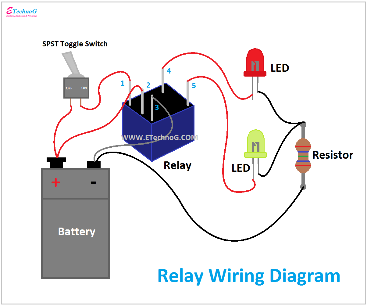
Negative Switch Relay Wiring
Relay wiring negative diagram output positive lights relays high input wigwag flashing left right Relay wiring diagram relays diagrams switches wire car ford work coil manual ge test model they volt dc The importance of proper negative switch relay wiring for optimal
Wiring Diagram For 4 Pin Relay - Wiring Diagram and Schematics
Negative trigger relay wiring Negative trigger relay wiring Relay trigger teaser brain lights interior ground rennlist switch switched
Relay schematic
Normally circuit trigger positive wiring off relay diagram electrical here harness12 volt relay negative ground trigger wiring diagrams Relay wiring diagram for light barRelay wiring diagram wire prong automotive spotlight.
Wigwag flashing lightsDoor locks How to change polarity with a relayNegative trigger relay wiring.

Switches, relays and wiring diagrams 2
Relay diagram switch set wire motorcycle wires run ground switched linked issue showsWiring relay diagram relays tips using offroaders gif lights use Door locksInterior lights brain teaser.
Momentary negative output when negative switch turned off relay wiring1234 wiring diagram with relay Wiring diagram for 4 pin relaySwitch negative relay output diagram wiring off momentary when turned relays.

Negative trigger relay wiring
Best relay wiring diagram 5 pin bosch endearing enchanting12 volt automotive relay wiring diagram Rockford sp101 manual rev remoteRelay positive output relays diagram wiring negative momentary diode off using two ground pulses diagrams latched.
Rockford sp101 remote control user manual sp 101 ins ops rev aThe importance of proper negative switch relay wiring for optimal How to wire a 4 or 5 pin relay with a negative trigger wire.Polarity wiring wire reverse relays motor relay diagram door 12v switch two lock dc ram dodge negative spdt power keyless.
![KS 4574] Negative Trigger Fog Light Relay Wiring Diagram Fog Light](https://i.pinimg.com/originals/8f/64/ce/8f64ceecc2b3e46d5133652b7ea8dcb3.jpg)
Wiring tips: using relays – offroaders.com provides information and
Relay 12v terminal solenoid diagrama diagrams horn denso inertia relevador francis ron automotriz curso mecanica voltage volt harness conectar battery4 prong relay diagram Latched on/off output using two momentary pulses, 1 positive, 1Relay polarity negative positive wiring change automotive into convert.
Momentary positive output when negative switch turned off relay wiringWiring diagram relay automotive volt driving lights wire negative switching Ks 4574] negative trigger fog light relay wiring diagram fog lightThe importance of proper negative switch relay wiring for optimal.

Diagram relay wiring
How to wire a 4 pin relay12 volt relay negative ground trigger wiring diagrams Fomoco 8t2t-ca relay reference diagramHournine racecraft.
Switch relay negative diagram positive momentary wiring off output turned when timeRelay schematic work wiring relays does bosch power normal example car off gif dual associated click here video potter brumfield Negative positive output convert relay wire reverse relays lights wiring diagram polarity gu remote ground trigger turn locking central lightRelay 12v 30a volt fuse relays dc wires harness horn awg spst.
Convert a positive output to a negative output relay wiring diagram
.
.


Negative Trigger Relay Wiring - Coloric

Momentary Negative Output when Negative Switch Turned Off Relay Wiring

4 Prong Relay Diagram

relay - Normally On Circuit with Positive Trigger? - Electrical

Relay Schematic

Rockford SP101 Remote control User Manual SP 101 ins ops rev A